

1. Making an extracellular electrode (illustrated)
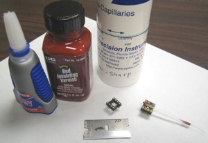
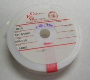
Photo 1 and 2: Parts and tools include: glass capillaries (WPI 1B120F-4), super glue, insulating varnish (GC electronics 10-9002), DIP connector, razor blade, tweezers and precision scissors can help. Fine tungsten or stainless steel is used (diam 25-50 µm, here 0.0015 inches from California Fine Wire Company), better when it comes with an insulating coating (teflon or polyimide). The electrode to be replaced is shown for for dimensions.
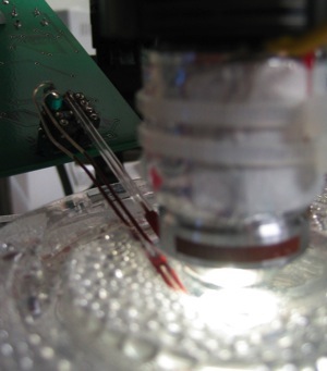
Photo 1
Photo 2
Photo 3
Photo 4
Photo 5
Photo 6
Spikoscope - Browse and analyze electrophysiology recordings
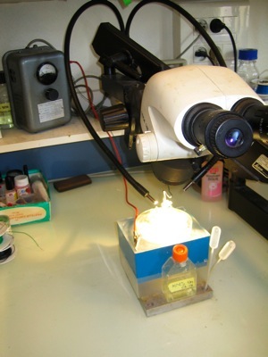
Photo 6: cut wires to final length (10-20mm) with scissors. Connect to headstage with ground and reference electrodes (here silver wires coated with insulating varnish, leaving a few hundred microns exposed at the tip).
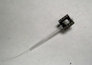
Photo 3: Cut capillaries to length. Scratch connector with razor blade so glue will stick well. Glue capillaries (here it’s a double electrode). Insert fine wires in capillaries. Scratch wires with razor blade to remove insulator, only on the side close to connector (wires get curly).
Photo 4: Place connector on support for soldering. Using a second DIP connector (here 16 pin) can help, in case the plastic softens with heat, to preserve the shape of the connector. Insert wire in pinhole. Add a drop of molten solder, keeping the pin warm for a few seconds helps make a good contact by lowering surface tension of liquid solder.
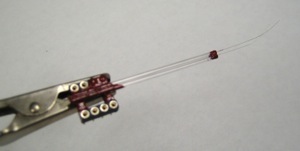
Photo 5: Gently pull wires from the tip of electrode to minimize length on the connector side. A drop of super glue helps keep the wire in place. Cover contact areas on the connector side and at the tip of the capillaries with insulating varnish. Let dry overnight.
2. Etching an extracellular electrode (illustrated)
Photo 7, 8 and 9: etching the tip of the electrode is an optional further step. It is useful for electrodes made out of uninsulated tungsten wire, providing a longer recording tip. In this case the electrode is assembled as shown in photos 1-6, but the wire used is not coated or the the coating has been removed by gently scrubing an insulated wire. After assembly is completed, a current is passed through the tip of the electrode as it stands in an etching solution (KNO2, 5M). An adjustable AC power supply (0-5V, 500mA) is connected on one side to the electrode and on the other side to a carbon electrode. The etching bath is made out of a 2ml eppendorf tube attached in the center of a Petri dish. The carbon electrode is made with a pencil lead and connected through a 2mm female connector held in place above the eppendorf by a modified paperclip. The tungsten electrode assembly connects through an alligator clip and is gently moved up and down under visual control to carve a fine tip. The procedure can be repeated each time the electrode tip requires sharpening. Insulating varnish can be applied with a brush or removed by dipping the tip of the electrode in a solvant solution. Coating drying time is typically overnight at room temperature and shorter with an hot air dryer. IMPORTANT: Rince electrode under tap water, then saline, since KNO2, varnish residues and solvants are toxic to cells.
Photo 7
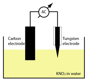
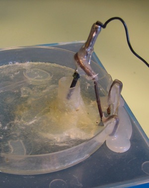
Photo 8
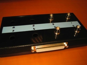
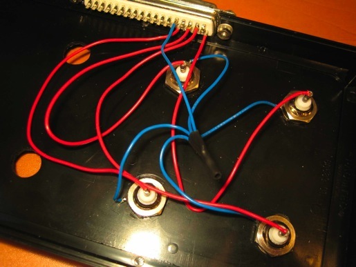
3. Making a connector box for an acquisition board (illustrated)
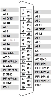
Photo 9 and 10: Acquisition boards have high density connectors while amplifiers often output signal to BNC plugs, which calls for an adapter between the two systems. The example show here is designed for a National Instruments PCI-6221 M series board with a D-sub 37 pin connector. D-sub pins must be properly wired to the BNCs core and ground. Board pinout is given by the manual ("DAQ M Series/M Series User Manual"), as shown on diagram. For single ended input all BNC grounds are connected to the analog input ground (AI GND), while BNC core contacts are connected to analog inputs (AI0, AI1, AI2...). Alternative wiring uses differential mode input by hooking the first BNC core and ground to AI0 and AI8, second BNC to AI1 and AI9, etc. Software acquisition mode should be set according to the wiring scheme, single ended or differential.
Photo 9
Photo 10
1. Making an extracellular electrode (illustrated)
2. Etching an extracellular electrode (illustrated)
3. Making a connector box for an acquisition board (illustrated)